In order to improve the accuracy and reliability of ultrasonic nondestructive testing, this paper studies the several component of the ultrasonic transducer, namely the two-component transducer and three-component transducer, analyzes and discusses the ultrasonic method in acoustic emission detection and the application of the stress tests.
Keywords ultrasonic transducer, acoustic emission
1 introduction
Ultrasonic transducer is the ultrasonic nondestructive testing of key components of the transformation between electricity - sound energy. The stand or fall of it not only determines the comprehensive technical performance index of detection system, and the correctness of the test results and reliability have great influence.
Acoustic emission testing, for example, by the acoustic emission source signals reach the surface of the transducer, can generally be broken down into a longitudinal vibration of vertical and a horizontal shear vibration and the shear vibration can be further broken down into two perpendicular polarization plane of shear vibration. Adopt the general acoustic emission transducer can only receive the longitudinal vibration of the component, thus lost the information brought by the shear vibration component.
Such as ultrasonic testing stress and residual stress, not only requires precise determination of the longitudinal wave velocity, material and accurate determination of two perpendicular polarization plane of shear wave velocity. Using multiple transducer, it is difficult to guarantee the test position is the same as the coupling conditions, thus affecting the test accuracy.
To this end, this paper studies the two-component and three-component transducer, analysis, testing their electric and acoustic characteristics, and discusses their application in acoustic emission detection.
2 research of two-component transducer
A two-component transducer is to the point, send and receive a shear wave and a longitudinal wave, or two perpendicular polarization plane of shear wave ultrasonic transducer.
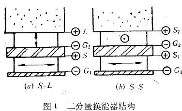
Two-component transducer by superposition of two pieces of chip, namely in shear wave transducer on the basis of adding a longitudinal wave chip two-component transducer (S - L) or a polarization plane vertical shear wave chips (S - S two-component transducer), two kinds of transducer structure as shown in figure 1. Considering the two pieces of chips not line, at the same time to avoid signal interference between chips, insert a acoustic impedance between two chips near, through good sound insulation.
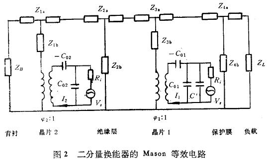
Due to the shear wave transducer are similar to those of p-wave transducer Mason equivalent circuit, it can export two-component transducer equivalent circuit shown in figure 2, which is suitable for insulation layer capacitance C '.
Each wafer receiving or with its corresponding ultrasonic launch, and is not sensitive to other components of the signal. So before considering a piece of crystal, equivalent to the original single chip transducer between the chip and backing adds a perforated layer (called acoustic layer after); Similarly, for after a chip is equivalent to increase before a perforated layer. Such as considering the chip 1, I2 = 0, the chip 2 transformer right half removed, can derive the chip 1 sound pressure when firing frequency response:

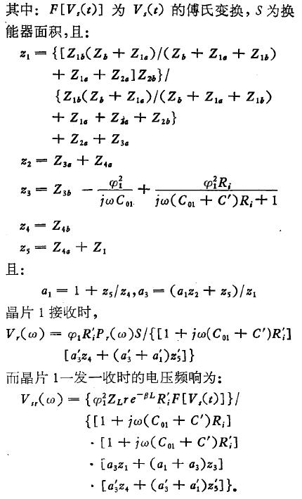
Similarly, when considering the chip 2, make I1 = 0, the chip shear wave 1 transformer right half, chip can be deduced and 1 similar results.
According to the above equivalent circuit of transducer can be calculated separately before and after perforated layer effect on the transducer. The results show that the acoustic layer causes sound waves to multiple reflections inside the transducer, along with the introduction of formed multiple pulse. Acoustic reflection pulse with initial fat layer before at same phase, then perforated layer reflection pulse in contrast to the initial pulse phase.
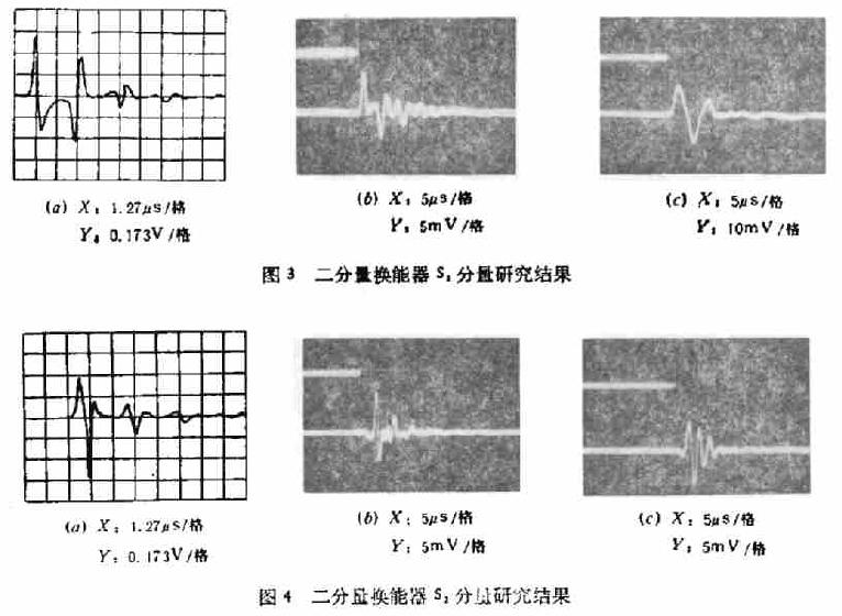
Because of the two-component transducer for multiple reflection pulse, brought inconvenience to the use of it. Considering the characteristics of the transducer has certain perceptual and capacitive area, therefore in series or parallel inductance capacitance transducer electrical end components can change the frequency characteristics and impedance characteristics, so as to achieve the purpose of improving its echo pulse. At the same time use heavy damping absorption backward propagation of sound energy is also backing some effective ways to reduce reflections pulse. The practice proved: the two-component transducer electrical end certain inductance in series, in parallel, and the heavy backing damping, can effectively improve the pulse characteristics. Figure 3, figure 4 S - S respectively before the two-component transducer after a component (S1) and a component (S1) under step pulse excitation to launch the results of the study, in which (a) as the theory of computer; (b) is measured; (c) for the waveform after series inductance.
Research of 3 three-component transducer
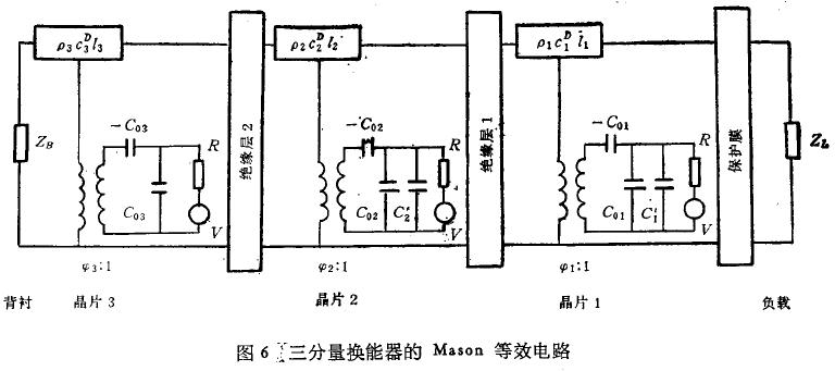
Shear wave are discussed above (S - L) a longitudinal wave and shear wave all variable wave two-component transducer (S - S), combine both further, comprise the three-component transducer. Are the two polarization direction perpendicular shear wave chip and a longitudinal wave chip stack, make it can simultaneously transmit to receive two direction of shear wave and a longitudinal wave. The structure of the three-component transducer as shown in figure 5, its corresponding Mason equivalent circuit is shown in figure 6.
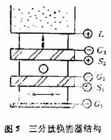
Obviously, for three-component transducer S1 and L amount of calculation and analysis and two-component transducer are similar, for the middle a sound chip, because at the same time by the acoustic reflection acoustic wave before and after stacking effect, the result is more complex. But according to the equivalent circuit of the computer and the measured results can be seen that under the condition of light backing, by acoustic layer after layer reflection of sound waves than the acoustic reflection waves. So measures used to improve the two-component transducer also suitable for the three-component transducer, which USES electric matching technology and heavy backing absorption block can achieve the goal of improving transducer pulse.
4 transducer acoustic field characteristics
Transducer of the sound field characteristics, especially in the far field directivity is one of the main features of transducer. Of circular piston p-wave transducer directivity predecessors has been underway for more in-depth research, to similar to the square shear wave transducer, can calculate various kinds of shear wave velocity mode transducer directivity. Compared with the actual test values that shear wave transducer vibration velocity model close to the binomial distribution.
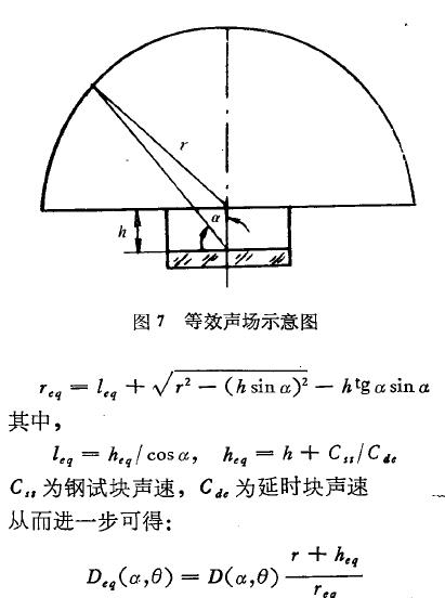
But in two-component and three-component transducer, due to the front of the wafer to the back of the chips have delayed effect, therefore adopted the approach of DengXiaoSheng field revised its directivity, which is equivalent to the first piece of chip at the back of the chip location of the sound field (see figure 7).
When considering the far field directivity, the sound pressure is inversely proportional to the distance, which can be:
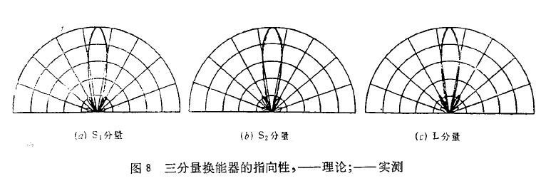
The revised two-component and three-component transducer directivity of theoretical calculation agree well with the measured results, as shown in figure 8 for the research results of the far field directivity of the three-component transducer.
5 new transducer in the application of acoustic emission testing
At present the widespread use of acoustic emission transducer can only receive the longitudinal vibration of acoustic emission signal, lost the shear vibration component. And shear vibration polarization resistance, often with some information of the sound source, testing shear wave transducer, found that after receiving acoustic emission signal receiving amplitude and its polarization direction of the shear wave transducer, when the polarization direction pointing in the direction of the sound source, receiving the highest amplitude; Conversely, when the sound source on the perpendicular polarization direction, receiving the lowest amplitude.
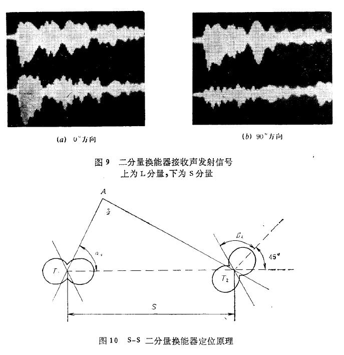
However, the size of the actual acoustic emission signal strength is uncertain, so rely on a single shear wave transducer to determine the direction of the sound source and eliminate noise and shortcomings. If using S - L two-component transducer to the transverse vibration and longitudinal vibration of acoustic emission signal component at the same time, will bring great convenience to test. As shown in figure 9 for two-component transducer S - L the results of the direction of different tones to launch reception.
Visible S - L waves of two-component transducer component (L) the omnidirectional, and shear wave component (S) has a direction. By comparing the S components and L the two signals, it is easy to identify the sound source direction; In the area of monitoring, S - L the direction of the two-component transducer is the monitoring area, which can effectively reduce the influence of other direction interference signal, and thus greatly improve the signal-to-noise ratio of testing.
Due to the transverse vibration of acoustic emission signal component with the sound source direction this information, using it can determine the direction and location of sound source. To shear wave all variable wave two-component transducer (S - S) receive the acoustic emission signal, the results show that: although the direction of the acoustic emission source, distance and intensity is to first uncertain, but S - S two-component transducer two components to the same signal amplitude response than only related to the direction of the sound source. Through the calibration can be set in advance of the transducer response curve of amplitude ratio corresponding to the direction of the sound source direction, in the form of polar coordinates description is the dumbbell shape (see figure 10), when receives a signal, according to the response curves of amplitude ratio and directional source possible four directions can be set.
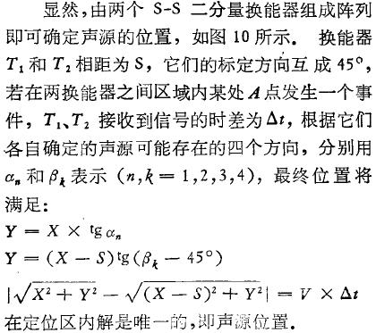
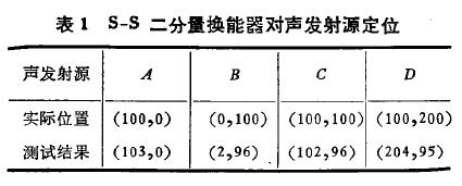
The T1, T2 two S - S two-component transducer according to the figure 10 layout on the large slab block, acoustic emission experiment was carried out in different locations, respectively with the sound source location of the computer processing test results and the actual sound source position as shown in table 1, visible S - S two-component transducer has good positioning effect on sound source.
6 the conclusion
Ultrasonic transducer are key components in ultrasonic nondestructive testing, this paper studies the two-component and three-component ultrasonic transducer, transducer electrical, acoustic characteristics of theoretical analysis and practical research has achieved consistent results. The transducer is directional, informative, coupling stability etc., can greatly reduce the ultrasonic stress test method for testing the location and the change of error of coupling conditions. In acoustic emission detection, because of increased shear vibration information receiving and analysis, thus to simplify the beamformer, directional, provides a new method to improve SNR.
References (abbreviated)


