Ministerial funded project, the author studies the tool breakage when the acoustic emission signal [1 ~ 3], this paper proposes a new monitoring method of anti-jamming is strong, corresponding new monitoring system is developed. Sensor, preamplifier, signal processing, the system, control system integration, using liquid transmission of acoustic emission wave, can be directly installed in the machine tool spindle. Layout of power supply, circuit board wiring and components anti-interference measures were taken. According to the principle of electromagnetic compatibility design at the same time, take a little bit of grounding, shielding shell structure.
1 noise interference in machining
In machining process, because there are a large number of acoustic emission phenomenon, such as three plastic deformation and friction between metal cutting deformation area, chip breaking, shaft gear meshing, rolling bearing vibration, therefore necessary acoustic emission signals produced by them with the tool breakage of the acoustic emission signal, and the tool breakage AE (&) emission signal outside noise removal.
Test used to cooling lubricants for media of contact with the surface of the acoustic emission sensor, the sensor will preamplifier (4 MHZ bandwidth, gain 60 db) integrated internally, high sensitivity, the transmission amplitude frequency characteristics are shown in figure 1. Figure in the y coordinate for G/dB. Sensor resonance frequency is 1 MHZ, the chart shows, in the following 4 MHZ frequency range has good transmission characteristics. Data collection using the highest sample frequency of 5 MHZ data acquisition boards. The tool breakage signal and the main interference noise are collected and stored in the computer, and then use the signal processing software to analyze it.
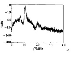
Figure 1 sensor transfer characteristic figure
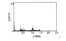
Under the actual working condition of interference mainly from the following two aspects: (1) disturbance signal of the sensor shell series, including heavy impact sensors (e.g., workpiece handling, tool change, etc.), shaft gear meshing, rolling bearing vibration noise and flying debris impact sensor, etc.; (2) in normal cutting three cutting deformation of plastic deformation and friction between metal and acoustic emission signals generated by chip breaking, etc. Interference noise power spectrum (S) as shown in figure 2, figure 3.

Figure 2 sensors by the impact of interference noise power spectrum
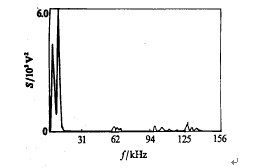
For heavy interference caused by the impact sensor noise power spectrum analysis, the noise energy is larger, but mainly in the low frequencies, at the same time with less energy of high frequency components. Flying debris impact caused by the sensor noise is concentrated in low frequency band, but the proportion of signal energy to impact sensor is small about 3 orders of magnitude. Shaft gear meshing vibration noise power spectrum distribution of the basic and heavy impact sensor are similar, but relatively small signal energy to about two orders of magnitude.
By figure 4 shows, chip breaking when the interference of noise frequency range is wide, but relatively low frequency band energy (excluding the influence of the sensor resonant frequency band). To get normal cutting (no chip breaker) of AE signal, the use of high speed steel and carbide tool with different cutting parameter turning medium carbon steel, and acquisition of AE signal, a typical signal as shown in figure 5. The signals for continuous appear in small increments, power spectrum analysis shows that its energy is concentrated in the high frequency above 100 KHZ. From the above two cases, the AE signal produced by normal cutting energy is smaller.
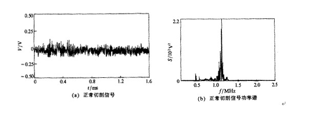
As shown in figure 6 typical AE signal of tool breakage and its power spectrum diagram, for greatly the pulse signal of time domain, the duration of 0.2 ~ 1.0 ms. From a large number of tool breakage AE signal power spectrum statistical analysis shows that within the scope of 0.1 to 2.0 MHz signal distribution. Features against the sensor, the subsequent processing circuit filter cutoff frequency of up to 0.3 ~ 0.4 MHz, this to improve the tool breakage acoustic emission detection of anti-jamming is helpful. As can be seen from the tool breakage power spectrum diagram, its power spectrum energy than normal cutting the power spectrum of big about 3 orders of magnitude.
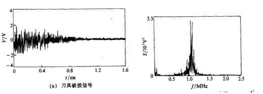
From the above analysis, to distinguish tool breakage and all kinds of jamming signal, the signal should be from the acoustic emission signal frequency, amplitude, duration and other aspects were identified. Basic can be ruled out from the band weight and flying debris impact sensors, such as spindle speed by sensor shell conduction disturbance signal; Can rule out the normal cutting and chip breaking from the energy produced by the AE signal. So as long as it can identify the frequency of the acoustic emission signal, the length of the amplitude, duration, and can identify tool breakage.
On the basis of the above tool breakage principle of acoustic emission signal identification, acoustic emission signal processing method as shown in figure 7.
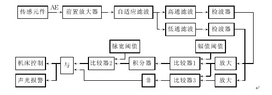
Due to the tool breakage acoustic emission signal frequency is high, so use the high-speed signal acquisition unit to extract to the original acoustic emission signal, but if the envelope signal collection and processing can reduce the requirement for subsequent recognition processing circuit. As shown in figure 7, through the detection of signal amplitude to identify to identify the AE signals, and then through pulse width identification of AE signal duration, i.e. the amplitude and pulse width of double threshold criterion can identify tool breakage of the acoustic emission signal. In order to eliminate the interference of the conduction by the sensor shell, this system USES an adaptive filter, the shell conduction interference of the noise by filtering. And then the signal into high and low pass filter respectively, then comparing two road after the signal is amplified by detection, at the same time to qualcomm signal envelope amplitude comparison (detection). When the envelope signal reaches preset amplitude threshold, the comparator 1 trigger flip. Then compare pulse width, the signal into the integrator to integral. Only 1 of the comparator flip signal accumulated a certain amount of time, the output of the integrator is higher than the preset threshold value, pulse width 2 will trigger comparator flip (when the integrator output is lower than the pulse width threshold, considered the impact interference). In addition more than when the envelope signal of low-pass qualcomm envelope signal, 3 trigger comparator flip. The comparator 2 and 3, the logic of the output signal of comparison "not" logic "and". That only when the comparator is greater than 2 trigger flip and qualcomm envelope signal to a low-pass envelope signal, logic "and" just as the "true", the result of the alarm signal is given. Through the logic behind "and" function to eliminate the strong low frequency noise, at the same time with the weaker high-frequency interference (such as heavy impact sensor). To reduce the false alarm in the practical application.
Due to the sensitive element is immersed in the liquid cooling and lubrication, and emulsion has a certain electrical conductivity, so all kinds of high-voltage electrical interference noise will pass it to the conduction sensitive element; Additional sensors installed in the cooling lubricant flexible pipe roots and sound waves to use cooling lubricants a longer path to reach the sensor. Signal attenuation in the process of transmission, so the sensor has high sensitivity. In order to eliminate the interference of high voltage, at the same time also to coupled acoustic signal, in the sensitive element surface coated with a layer of insulation glue, the thickness shall be the acoustic coupling medium wavelength 1/4 of an odd number of times. Experiments and practical application proved that the anti-jamming measures are effective. To reduce the thermal noise of the system, make the cooling lubricant circulation through the electronic chamber, by reducing its internal temperature to reduce the noise of the circuit. Voltage noise is caused by thermal noise of device, usually with the mean square value, "says the Un = 2 (kTReB) 1/2, type in the boltzmann constant k = 1.38 x 10⁻²³ jk - 1; T as the thermodynamic temperature of the device; B is the bandwidth of the device; Re the equivalent resistance of the input stage to the device. In this design can reduce electronic chamber temperature 10 ~ 20 ℃, thereby effectively reducing the thermal noise of the circuit. Monitoring and control system also adopts low noise (.vn 10 or less nv. Hz1/2) operational amplifier of preamplifier and main amplifier, these measures to further reduce the thermal noise, improve signal-to-noise ratio.
3 experiments and conclusion
In changchun FMS experiment center of MCV -o (NO. 1) vertical machining center, drilling and milling cutter breakage of the experiment on cutter test were conducted 22, 22 success. Bit test results see the table below.
Table drill breakage monitoring test results
|
Bit diameter /mm |
Spindle speed /(r.min-1) |
feed
/(mm.min-1) |
Number of test
|
Success rate/% |
|
0.2 |
1000 |
32 |
10 |
100 |
|
0.4 |
1000 |
13 |
20 |
100 |
|
0.5 |
1000 |
13 |
10 |
100 |
|
0.6 |
1000 |
20 |
10 |
100 |
|
0.8 |
1000 |
32 |
20 |
100 |
|
1.0 |
1500 |
13 |
20 |
100 |
|
1.5 |
1000 |
13 |
10 |
100 |
|
2.1 |
1000 |
20 |
5 |
100 |
During the experiment, human impact sensor shell and start-stop machining center spindle and machining center, such as variable speed did not cause false positives, experiments show its strong anti-interference, the development of acoustic emission tool breakage monitoring system has higher reliability, popularization and application value.


