技术与应用
发布日期:2015-04-22 09:09 浏览次数:次


| 伺服电机 | 步进电机 | |
| 控制精度不同 | 交流伺服电机的控制精度是步距角为1.8°的步进电机的脉冲当量的1/655 | 两相混合式步进电机步距角一般为 1.8°、0.9°,五相混合式步进电机步距角一般为0.72 °、0.36°。 |
| 低频特性不同 | 交流伺服电机运转非常平稳,即使在低速时也不会出现振动现象。交流伺服系统具有共振抑制功能,可涵盖机械的刚性不足,并且系统内部具有频率解析机能(FFT),可检测出机械的共振点,便于系统调整 | 步进电机在低速时易出现低频振动现象。振动频率与负载情况和驱动器性能有关,一般认为振动频率为电机空载起跳频率的一半。这种由步进电机的工作原理所决定的低频振动现象对于机器的正常运转非常不利。 |
| 矩频特性不同 | 交流伺服电机为恒力矩输出,即在其额定转速(一般为2000RPM或3000RPM)以内,都能输出额定转矩,在额定转速以上为恒功率输出 | 步进电机的输出力矩随转速升高而下降,且在较高转速时会急剧下降,所以其最高工作转速一般在300~600RPM |
| 过载能力不同 | 交流伺服电机具有较强的过载能力,具有速度过载和转矩过载能力。其最大转矩为额定转矩的二到三倍,可用于克服惯性负载在启动瞬间的惯性力矩 | 步进电机一般不具有过载能力,在选型时为了克服这种惯性力矩,往往需要选取较大转矩的电机,而机器在正常工作期间又不需要那么大的转矩,便出现了力矩浪费的现象 |
| 运行性能不同 | 交流伺服驱动系统为闭环控制,驱动器可直接对电机编码器反馈信号进行采样,内部构成位置环和速度环,一般不会出现步进电机的丢步或过冲的现象,控制性能更为可靠 | 步进电机的控制为开环控制,启动频率过高或负载过大易出现丢步或堵转的现象,停止时转速过高易出现过冲的现象,所以为保证其控制精度,应处理好升、降速问题 |
| 速度响应性能不同 | 交流伺服系统的加速性能较好,从静止加速到其额定转速3000RPM仅需几毫秒,可用于要求快速启停的控制场合 | 步进电机从静止加速到工作转速(一般为每分钟几百转)需要200~400毫秒 |
 (5-1)
(5-1)
 (5-7)
(5-7)


 。
。 。
。

 (5-10)
 式
式

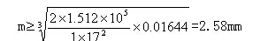
 Ft10;再将所得出的数据代入式(5-11)可得
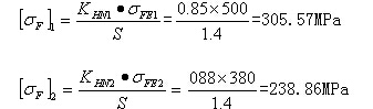
 时,直齿轮的弯曲应力在400~850MPa之间。

 (5-13)
 Qj----齿轮的接触应力(MPa);
 ;
; ;
; ----齿轮螺旋角(°);
 ;
; ----主、从动齿轮节点处的曲率半径(mm);
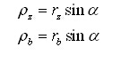
 Rz Rb分别为主从动齿轮节圆半径(mm)。
 作为计算载荷时,打印机齿轮的许用接触应力Pj
 =1998.61 MPa,符合渗碳齿轮1900~2000 MPa区间,因此,所设计打印机齿轮的接触应力基本符合要求。
 P=Tw=4.8*0.1/0.067=7.16W
 Ka=1.7。则计算功率为:
 Pca=KaP=7.16*1.7=12.17W

 Pb=12.7mm


 ,所以大带轮相关参数数据与小带轮完全相同。齿数
 Z2=29,节距
 Pb=12.7mm
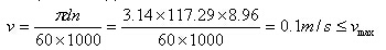


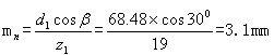
 Zm=20。
 的计算
的计算

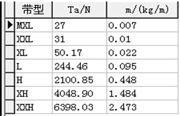
 Ta=2100.85N,m=0.448kg/m。


第七章 小结
桌面级3D打印机随着技术的成熟已经渗透到人类日常生活,也许将来某一天还能成为生活必不可少的一部分,给人们带来新的体验。对于我们还没有踏出校门的学生来说,桌面级3D打印机的设计有助于提高我们的设计水平以及实践能力。对于本次设计,其特点是:步进电机低速运行,没有大型机床的噪声,容易操控;不管是电机还是丝杆,亦或是光轴等,都充分参考了产品市场定价及规格,属于低成本制造,服务于大众,每个人都有能力购置这样一台3D打印机,市场潜力巨大;组装简便,此设计遵循DIY设计原则,符合广大DIY群体的需求,给制造商减去诸多负担,大大提高了生产率;零件构架不是很复杂,易于加工。当然,这次设计也有诸多不足之处,在产品选型方面,并没有严格按照计算所得来选择产品型号,而是在市场上寻找相似,功能可以相互替代的产品进行构建,所以,此方案可能更偏向于实际而非理论,故而缺乏一定的严谨性,在以后的学习和工作当中,我会继续研究桌面级3D打印机技术,力求将此方案设计的更加合理。一个学期紧张忙碌的毕业设计已经接近尾声,这次设计是对我大学四年来的学习的一次最综合的检验与考验,也是一次综合学习的过程。毕业设计不仅使我学习和巩固了专业课知识而且深刻了解了不少相关专业的知识,个人能力得到很大提高。同时也锻炼了与人协作的精神,为以后我踏入社会工作打下了良好的基础。
参考文献
[1] 刘伟军.快速成型技术及应用[M].北京:机械工业出版社,2005:1-13.
[2] 徐人平.快速原型技术与快速设计开发[M].北京:化学工业出版社,2008: 34-36.
[3] 汤酞则.材料成形工艺基础[M].长沙:中南大学出版社,2003: 221-226.
[4] 王文斌.机械设计手册.零部件设计常用基础标准[M].4版.北京:机械工业出版社,2007.
[5] 彭文生,张志明,黄华梁.机械设计[M].北京:高等教育出版社,2002:96-138.
[6] 闻邦椿,机械设计手册[M].5版.北京:机械工业出版社,2010.
[7] 赵又红,周知进.机械设计机械设计基础课程设计指导[M].长沙:中南大学出版社,2012.
[8] 刘鸿文.简明材料力学[M].北京:高等教育出版社,1997:254-259.
[9] 潘存云,唐进元.机械原理[M].长沙:中南大学出版社,2011.
[10] 朱孝录. 机械传动设计手册[M].北京:电子工业出版社,2007.
[11] [德]安德列亚斯.格布哈特.快速原型技术[M].北京:化学工业出版社,2005.
[12] 葛志祺.简明机械零件设计手册[M].北京:冶金工业出版社,1985.
[13] 濮良贵,纪名刚.机械设计[M].第七版.北京:高等教育出版社,2005:184-223.
[14] 王昆,何小柏,汪信远.课程设计手册[M].北京:高等教育出版社,1995:47-49.
[15] 侯洪生,王秀英.机械工程图学[M].北京:科学出版社,2001.
文献翻译
Feasibility Study of manufacturing using rapid prototyping: FDM Approach
1. Introduction
Prototypes are very important for realization of concepts in design, manufacturing and analysis. Prototyping isan essential part of product development and manufacturing cycle required for assessing the form, fit and functionality of a design before a significant investment is made.
Presently, a dominant technology for producing physical models for testing and evaluation purposes has beenrapid prototyping (RP). CNC prototyping has its own limitations involving the geometric errors due to machinetool accuracy and inaccuracy of machining and thermal errors arise due to frictional forces between the tool and thejob (Kosinar and Kuric 2011). Other disadvantages includes the loss of the raw material as the process issubtractive, the fixtures required in CNC machining have their different complicated designs for different types ofparts, increased costing due to manufacturing of valves and fixtures themselves, tedious programming associatedwith the CNC’s and hiring skilled labor for overviewing the process that adds to its cost (Lennings, 2000). Also theCNC machines are unable to manufacture parts with non-linear geometry or parts having complicated interiors.That’s where RP comes, introduced in the late 1980’s, are now established method of reducing work done onproduct development and its cost and lead times. Considering mass production CNC prototype may be cheaper but for manufacturing a single intricate product, RP prototype would have an upper hand.
The rapid prototyping processes can be broadly classified into processes that uses laser and ones which does not.The laser based processes requires high level of care and maintenance and the machinery is very costly ascompared to non-laser based processes. Fused Deposition Modeling (FDM) is second most widely used rapidprototyping technology, after Stereo-lithography (uses laser). In FDM a plastic filament is unwound from a coil and
supplies material to an extrusion nozzle which moves over the table in the required geometry and deposits a thinbead of extruded plastic to form each layer of the required geometry. Several materials are available for the processincluding Acrylonitrile-Butadiene-Styrene (ABS) and investment casting wax. ABS offers good strength, and morerecently polycarbonate and poly (phenyl) sulfonic materials have been introduced which extend the capabilities ofthe method further in terms of strength and temperature range ( , 2010). The most important mechanicalproperties of ABS are impact resistance and toughness which has tensile strength of 22MPa and tensile modulus of1,627MPa. Also the flexural strength of ABS is 41MPa and flexural modulus of 1,834MPa with IZOD Impactstrength of 340 J/m. It also resists heat successfully with its glass transition temperature of 104 degree Celsius andheat deflection temperature of 96 degree Celsius. Support structures are fabricated for overhanging geometries andare later removed by breaking them away from the object. A water soluble support material which can simply be washed away is also available.
A high level of intricacy can be obtained by this method depending upon the thickness of the layers withdimensional tolerances of +/-0.005” for the first inch and +/-0.002” for each additional inch. In the z-height(vertical), standard tolerances of +/-0.01” for the first inch and +/-0.002” on every inch thereafter are observed. Thestandard resolution: 0.01”; Minimum wall thickness is 0.02” ( , 2010). On making intricate parts we shouldnot only think about the intricacies in design and shape but also about different sections including thinner ones
which are more vulnerable to failure due to resilience and capacity to sustain other natural and manual forcesincluding thermal forces. The advantage of FDM is that the material has good capacity to handle heat and otherdemanding product tests. It is a feasible option for both rapid prototyping and rapid manufacturing which meansmanufacturing using RP and producing parts that are both accurate and durable
2. Rapid Prototyped Sand Casting
The RP pattern made can be used as a pattern in sand casting. It is useful when the shape of the parts is intricate,when metal or wooden pattern cannot be made. For example, a pattern of Funnel shown in the Figure 1 has apeculiar shape and contours which are not only thin but complex and difficult to be crafted on wood as the sectionsare thin. Also the pattern cannot be made by metal due to its peculiar shape. Therefore a RP part is made which canbe then further used to create a master pattern, usually made from aluminium, for sand casting. Another examplecan be taken when the pattern needs to incorporate core prints within the pattern which are sometimes delicate andsmall. This could be problematic while using the wooden patterns as it might not be possible to create them inwood due to their tiny shape and neither in metal as it may require extreme precision. Therefore, again the RPmethod can be used to create the Core Prints in the RP part easily. Medical parts that are used for implant are very good examples of the intricate and delicate parts that are to be casted and RP method are very useful in those cases.
3. Using Rapid Prototyping for Investment Casting
This new process of investment casting (Lost RP Part Casting) is totally different and a lot easier than theconventional investment casting (Lost Wax Casting). It does not require any ‘die’ to make any wax patterns,neither the process of ‘Pattern Assembly’ is required here. The problematic work of consecutive dipping of thepattern assembly to make a thick ceramic shell is also avoided by using this process. Actually in this process, theRP part itself is used as a pattern instead of a wax pattern which is then further used for casting the metallic part(Kosinar and Kuric 2011). The most important advantage is that the method has been successful in getting rid ofthe cores. Designing cores and placing them in the mouldbox are one of the most difficult tasks and requires muchgreater accuracy (Frank et al. 2003). Therefore, this new type of investment casting has done away with all theproblems that needed to be faced while dealing with cores. Unlike conventional investment casting, where thegating system and the feeders are attached externally to the pattern, the RP pattern here incorporates the gatingsystem and feeders. The RP pattern used for sand casting and investment casing is different in the fact that the RPused for sand casting does not have the gating system and feeders and is just a model of a finished product.
4. Costing
The comparison of costing of the sand and investment casting is made by the following cast studies of themiddle disc of Oldham coupling. The following are the deductions made from of costing of both sand andinvestment casting (for one part)
The tooling cost is more in case of sand casting due to extra defects like sand particles inclusions in the surfaceand more errors in dimensional allowances whereas we get mores surface finishing in case of investment casting.The Cast metal Cost of the sand and the investment casting are nearly same because Cast metal costing depends onthe dimensions of the casts prepared which are same in both the cases. The tooling cost is lower in case ofinvestment casting as the surface is smoother in this case because the sand particles does not stuck to the surface of the metal part which is a problem in sand casting sometimes.
The total material costing in investment casting is much greater than that of sand casting due to the materialused to make the slurry and the wax that is used in case of investment casting which is too costly as compared toGreen Sand in case of sand casting. Also the pattern is a onetime investment in sand casting unlike investment casting.
We had not evaluated the energy and labor cost but we can say that the energy cost may be high for theinvestment casting as the RP part needs to be baked on muffle furnace that works on electricity and consumes lotof it. Also the RP pattern for investment casting consumes more electricity due to its bigger size than sand casting.We can also guess about the labor work which may be high for Sand casting as extra labor is required for makingmold and preparing sand and proper ramming of the sand. Labor for pouring and other petty works are common for both.
Total cost for sand casting is much lower than that of investment casting but the ease of doing the process, thefinishing of the cast and to get the cast of least defects one has to follow the process of investment casting. To get Zero-Defect-Casting at one go one has to use the process of investment casting.
5. Conclusions
RP pattern can be used in sand casting when pattern making is troublesome meaning that the design of the pattern is complicated which is not possible to make in wooden or metallic forms. They can be successfully used inmass production after making a metallic master pattern usually made of aluminum or by spraying layers of metal over the pattern.
使用快速原型制造的可行性研究:FDM方法
摘要
这项工作的目的是根据客户的突发奇想在制造行业带来一场从大规模生产制造到特制的制造业产品的生产的革命。为此,快速原型(RP)方法用于生产铸造产品原型或模型。运用RP技术进行铸造的一种新方式:熔融沉积制造(FDM)。RP部件同样也应用于砂铸件的测试。名为“AUTOCAST-X”的软件被用于设计和模拟零缺陷铸件。曾有一个关于十字滑块联轴器的中间圆盘的案例研究,圆盘的生产使用新方式铸造和沙子铸造和部分由两种方法进行了比较。铸造人员记录在沙模铸造中使用RP的观点。他们发现它有助于那些不能由一个模式在木材或金属制造商中进行错综复杂的图案设计。
关键词:定制生产;AUTOCAST-X;快速成型;熔融沉积造型
1. 简介
原型对于实现概念设计,制造和分析是非常重要的。原型是在进行重大投资之前进行产品开发和制造周期评估,适应和功能设计的重要组成部分。
目前, 快速原型(RP)已成为生产物理模型进行测试和评价的一种主要技术。数控原型有其自身的限制, 由于机器工具精度和加工误差和由于工具之间的摩擦力工作产生的热错误导致几何误差。其他缺点还包括原材料的损失,相关数控编程的繁琐以及招聘熟练工人导致的制造成本增加以及为不同类型的零件、阀门和设备做不同的复杂的设计也导致原材料的损失。数控机器也无法生产部分非线性几何或部分有复杂的内部结构。在1980年代末有快速原型出现的地方,现在都建立起可以减少产品开发成本和交货期的机制。考虑大规模生产数控原型可能便宜但制造一个复杂的产品,RP原型会占得先机。
快速成型过程大致可分为使用激光的和那些相比于非激光流程价值更昂贵的需要高水平的护理和保养的机械不基于激光的过程。在使用激光方面,熔融沉积制造(FDM)是应用第二广泛的快速成型技术。在熔融沉积制造中,从线圈上解下来的塑料丝通过在所需几何平面以及挤压材料形成每一层所需几何平面上移动的挤出头挤出原材料。有些材料包括丙烯腈-丁二烯-苯乙烯(ABS)和熔模铸造蜡。ABS提供良好的强度,以及更多可以拓展力量和温度范围的聚碳酸酯和保利(苯)磺酸材料。最重要的机械ABS具有耐冲击性能和韧性,可以承受22 mpa的拉伸强度和1627 mpa的拉伸强度。同样的,更强力的ABS可以承受41 mpa的挠曲强度和1834 mpa340 J / m的悬臂梁式冲击力量下的弯曲模量。同时,它也能承受104摄氏度的热的玻璃化转变温度以及96摄氏度的热挠曲温度。支持结构悬臂几何图形和制作后来也被他们攻克。可以流动的溶于水的支持材料也诞生了。通过调整每一层厚度的尺寸公差,即第一层为+ / - -0.005,第二层为-0.002 + /,可以解决高水平的复杂性的问题。在Z轴方向的精度控制在0.01,最小层厚为0.02.对于复杂的部分,我们不仅考虑错综复杂的设计和形状,也要考虑由于韧性和包括热在内的自然和人工力量的维持而导致稀释剂的不同而更容易失败。FDM的好处是,该材料具有良好的能力来处理热等要求产品测试。使用RP生产和精确生产对于快速原型和快速制造来说是一个可行的方案。
2. 快速原型砂铸造
RP模式也可以用作砂铸件。当金属或木制的模式不能生成零件时它是有用的。例如具有模式独特的形状和轮廓的漏斗,不仅薄,复杂,而且很难将最薄的木质部分制造出来。同样由于其特殊的形状也不能由金属生成。然而快速成型却可以创建一个由铝生成的砂铸件的模式。同样的,如果模型需要从内打印或者特别小也适合。在使用木制的模式可能会有问题, 因其微小的形状它可能不可以创建,因为它不可能需要极端的精度。因此, 再次RP方法可以用来创建RP的核心输出部分。医疗部分, RP方法在植入错综复杂和微妙的部分非常有用。
3. 对熔模铸造使用快速原型
这种新工艺的熔模铸造(失RP部分铸造)是完全不同的,也比传统的熔模铸造(失蜡铸造)容易得多。它不需要任何蜡模式,也不需要组装模式。那些需要连续工作组模式做出厚陶瓷壳的工艺容易出问题,所以也避免使用这一过程。实际上在这个过程中,RP部分本身是作为一个模式,而不是蜡模然后进一步用于铸造的金属部分。最重要的优势是,该方法已经成功地摆脱了核心。设计核心并将它们放到模具中是一个最困难的任务并要求更大的准确性。因此,这种新型的熔模铸造已经废除了在处理核心时所有需要面对的问题。不同于传统的熔模铸造的浇注系统和馈线连接外部模式,RP这里包含控制模式系统和喂食器。RP模式用于砂铸造和投资套管在RP的事实是不同的用于砂铸造没有浇注系统和馈线和成品的只是一个模型。
4. 成本核算
通过对十字滑块联轴器的中间盘的研究比较砂铸造和熔模铸造的成本。下面是一部分成本的核算。
由于额外的缺陷如砂颗粒夹杂物的表面和对熔模铸造进行表面处理时产生更多的错误,砂铸件的加工成本占绝大部分。沙子和投资成本的铸造金属铸造几乎相同。因为铸造金属成本相同的情况下取决于铸件的尺寸。在熔模铸造的表面是光滑这种情况下工具成本是低的,因为沙子颗粒表面不粘的金属部分砂铸造有时也是一个问题。
熔模铸造的总材料成本远远大于砂铸件,因为用于制造所使用的泥浆和蜡的材料相比成本太高。而且沙模铸造的模式是一个一次性投资。我们没有评估能源和劳动力成本,但我们可以说,能源成本可能更高,熔模铸造RP部分需要在马弗炉烤,电力和工作消耗了许多它。RP模式投资铸造消耗更多的电能由于其规模比砂铸件大。我们也可以猜对劳动的工作可能高,因为砂铸件需要额外的劳动力模具和准备。对于二者来说,劳动投入和其他琐碎的工作都是很常见的。砂铸件总成本远远低于投资铸造除了缓慢的过程。完成改造最小的铸造缺陷必须遵循熔模铸造的过程。得到零失误的一口气使用熔模铸造的过程。
5. 结论
RP模式可用于砂铸造模式当遇到不可能在木制或金属形式完成的复杂的设计时。通常由铝或喷涂层的金属的金属主模式后他们可以成功地用于大规模生产。


 鹏翔新闻
鹏翔新闻
